Learning Objectives
The learning objectives for Lovable Linux are:
- Building Character
- Proving a Point
- Never Giving Up
ECE 391 vs. CS 341 #
A common point of contention among ECE and CS majors: “Is CS 341 harder than ECE 391?”. This has probably been debated, since the beginning of either course’s conception. Your TAs discussed this and wanted to settle this question once and for all. ECE 391 is known for their killer semester long final project, which is building an operating system from scratch. Normally a 391 student is given 6 weeks and 3 partners to finish this assignment, but since 341 students are superior programmers we feel that 1.5 weeks should be plenty of time to do this on your own. The rest of the documentation and starter code is transcribed from the actual assignment.
Introduction #
Read the Whole document before you begin, or you may miss points on some requirements (for example, the bug log).
In this machine problem, you will work in teams to develop the core of an operating system. We will provide you with code that boots you into protected mode, sets up the GDT, LDT, and initial TSS, and maps a read-only file system image into physical memory for you. You must set up the interrupt descriptor table (IDT), basic paging support for tasks, separate 4 MB pages for the kernel and applications, initialize a few devices, write the system call interface along with ten system calls, provide support for six tasks from program images in the file system which interface with the kernel via system calls, multiple terminals and basic scheduling.
The goal for the assignment is to provide you with hands-on experience in developing the software used to interface between devices and applications, i.e., operating systems. We have deliberately simplified many of the interfaces to reduce the level of effort necessary to complete the project, but we hope that you will leave the class with the skills necessary to extend the implementation that you develop here along whatever direction you choose by incrementally improving various aspects of your system.
Processor Initialization #
Load the GDT
You learned about the global descriptor table (GDT) in class. Linux creates four segments in this table: Kernel Code
Segment, Kernel Data Segment, User Code Segment, and User Data Segment. In x86_desc.S, starting at line 38, we
have created an empty GDT for you.
Write code that makes an emulated Intel IA-32 processor use this GDT. We have marked a location in the code (boot . 8 line 27) at which you will need to place this initialization code for the GDT to ensure that you follow the correct boot sequence. You will need to look through the ISA Reference Manual for information about how to write this code (https://courses.engr.illinois.edu/ece391/secure/references/IA32-ref-manual-vol-3.pdf)
Initialize the IDT
Your IDT must contain entries for exceptions, a few interrupts, and system calls. Consult the x86 ISA manuals for the descriptor formats and please see Appendix D for more information. The exception handler(s) should use the printing support to report errors when an exception occurs in the kernel, and should squash any user-level program that produces an exception, returning control to the shell (the shell should not cause an exception in a working OS)- see System Calls (Appendix B) for further details. You will also need to handle interrupts for the keyboard and the RTC. Finally, you will need to use entry ox8 0 for system calls, as described below.
Initialize the Devices
Adapt the initialization code from Linux to initialize the PIC, the keyboard, and the RT C. Set up a general-purpose infrastructure similar to what is done in the Linux kernel. You need to handle the keyboard and RT C interrupts, but you also need to make sure that these devices are initialized before taking interrupts. We suggest that you first mask out all interrupts on the PIC, then initialize the PIC, initialize the devices, and, as part of each device’s initialization, enable its associated interrupt on the PIC. The handler addresses should be installed dynamically/indirectly via a data structure used by the default handlers (as in Linux). You may also want to review the RT C data sheet linked from the class web page.
For the checkpoint, your OS must execute the test_interrupts handler (provided in lib.c) when an RTC interrupt
occurs. When a keyboard interrupt occurs, you must echo the correct characters to the screen. These simple tests will
determine if you have the IDT entries set up correctly, the PIC enabled, and the devices initialized and able to generate
interrupts.
Initialize Paging
As preparation for the next steps in the MP you must have paging enabled and working. You will be creating a page directory and a page table with valid page directory entries (PDEs) and page table entries (PTEs). More information about this process appears in Appendix C and in the Intel ISA manual linked from the class web page.
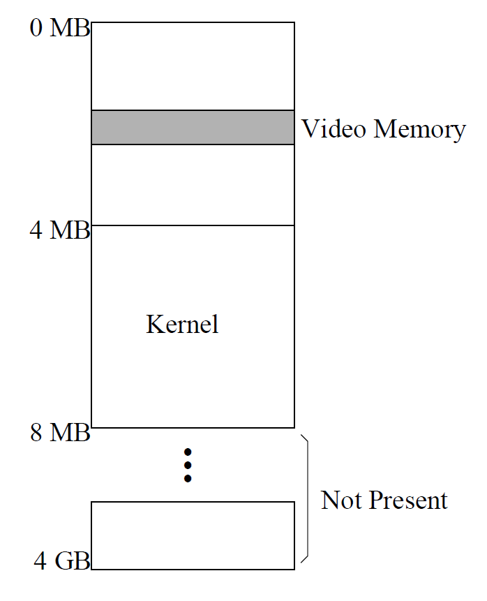
The image to the right shows how virtual and physical memory are laid out for this checkpoint. To keep things simple, the kernel and video memory will be at the same location in virtual memory as they are in physical memory. Your kernel code is already loaded at 4 MB for you, so you need only map virtual memory 4-8 MB to physical memory at 4-8 MB. This kernel page should be a single 4 MB page, whereas the first 4 MB of 4 MB memory should broken down into 4 kB pages. In addition to 8MB to 4GB being marked not present, you should also set any unused pages to not present as well. In this layout everything in Kernel the first 4MB, that isn’t the page for video memory, should be marked not present.
Make sure that you align your pages (page directory and page 8 MB tables) on 4 kB boundaries. To align things in x86:
.align BYTES_TO_ALIGN_TO
label:
(whatever you want aligned)
To align things in C:
int some_variable _attribute_((aligned (BYTES_TO_ALIGN_TO)
Troubleshooting/Debugging
See Appendix G for more information about debugging and common issues.
Handin
For this handin, we expect you to have written your own “blue screen” of death for each of the exceptions. At a
minimum, this screen must identify the exception taken. You may also want to read about how exceptions are handled
in the Intel ISA and print more useful information, such as the memory address reference that caused a page fault.
This information will be of use to you later for debugging. We expect you to be able to boot your operating system
with paging turned on and to enter a halt loop or a while (1) loop. Then we expect you to boot your operating
system and explicitly dereference NULL to demonstrate your “blue screen” identifying the resulting page fault. We
also expect you to be able to press a key and demonstrate that your operating system reaches the test_interrupts
function in on RTC interrupts, but you do not need to write a full interrupt handler for RTC yet, merely show that
you can receive interrupts. Finally, we expect your keyboard interrupt handler to echo the correct character to the
screen, although where each character appears on the screen doesn’t matter. As with the RTC, you need not write a
full interrupt handler for the keyboard for this checkpoint.
Device Drivers #
Create a Terminal Driver
When any printable characters are typed at the keyboard, they should be displayed to the screen. This includes handling all alphanumeric characters, symbols, shift and capslock, but you do not need to support the number pad. You will now need to keep track of the screen location for this purpose. You do need to support vertical scrolling (but not history) and will need to interpret CTRL-L (non-printable key) as meaning “clear the screen and put the cursor at the top” which will make your testing experience more pleasant. You do also need to support backspace and line-buffered input. The size of the buffer should be 128 characters for this checkpoint. For more details on how the terminal read and write functions should work, and how to handle the buffer filling up, please see Appendix B.
Keep in mind that you will also want to have an external interface to support delivery of external data to the terminal output. In particular, write system calls to the terminal should integrate cleanly with keyboard input. The hello program in the file system will eventually help to test the basics, but for now its source code will show you how user programs will pass parameters to your terminal.
Parse the Read-only File System
You will need to support operations on the file system image provided to you, including opening and reading from files, opening and reading the directory (there’s only one-the structure is flat), and copying program images into contiguous physical memory from the randomly ordered 4 kB “disk” blocks that constitute their images in the file system. The source code for our 15 program will show you how reading directories is expected to work. Also see Appendix A for an overview of the file system as well as Appendix B for how each function should work.
The Real-Time Clock Driver
You will need to write the open, read, write, and close functions for the real-time clock (RTC) and demonstrate that you can change the clock frequency. You will need to do some research on how the RTC works and what the device driver needs to do to communicate with it. Virtualizing the RT C is not required, but does make testing easier when you run multiple programs with the RT C open. Again, see Appendix B for how each function should work.
Handin
For this handin, you will need to demonstrate that your open, read, and write functions for the three device drivers work correctly. This functionality is independent of how your operating system may use the devices, but it is a good idea for you to start thinking about how you want to interface these functions with the corresponding system calls (see Appendix B).
You will need to show that when a key is pressed, the keyboard driver stores the corresponding letter in a buffer and that by explicitly calling the keyboard read function you can receive the correct letters and print them out on the screen. Similarly, you will need to demonstrate that you can change the rate of the RT C clock using the write function and that the read function returns after an interrupt has occurred. A good way of doing so is by having the RT C interrupt handler increment a counter and write to a specific spot on the screen.
Finally, you will need to demonstrate that you can read from the read-only file system. A good check for this test
is to use the xxd command, which prints a hexadecimal dump, to compare the output of your file system code with
the bytes stored in the file system image. Please note that you should run xxd on filesys_img and not the individual
executables; as your code reads from the filesystem image, its output might not directly match that of xxd run on the
individual executables. For the handin, you must have some test/wrapper code that given a filename, a buffer, and a
buffer length, will read data from the given file into the buffer.
System Calls and Tasks #
Support System Calls
Eventually, all ten system calls must be supported via a common IDT entry, so you will have to set up some generic assembly linkage along the lines of that used in Linux, including syscall value checking, register save and restore, and a jump table to C functions that implement the system calls themselves. The details of each call are provided in Appendix B.
For this checkpoint, you only need to support the system calls necessary to run testprint from shell: execute,
halt, and open/close/read/write for the terminal and filesystem.
Tasks
Programs execute to completion, so you need not write a scheduler or deal with the timer chip yet, but you do need to be able to squash programs if they generate exceptions, returning control to the shell in such cases.
As in Linux, the tasks will share common mappings for kernel pages, in this case a single, global 4 MB page. Unlike Linux, we will provide you with set physical addresses for the images of the two tasks, and will stipulate that they require no more than 4 MB each, so you need only allocate a single page for each task’s user-level memory. See Appendix C for more details.
Support A Loader
Extend the code for your file system driver to copy a program image from the randomly ordered 4 kB “disk” blocks constituting the image in the file system into contiguous physical memory.
This process is normally performed by a program loader in cooperation with the OS, but in your case will be performed completely within the kernel, since the file system code and control of the memory is internal.
In addition, you will need to set up the stack properly and then return into user-level, since privilege level 0 cannot call down into privilege level 3, and your user-level code must execute at the lower privilege level.
Executing User-level Code
Kernel code executes at privilege level 0, while user-level code must execute at privilege level 3. The x86 processor does not allow a simple function call from privilege level 0 code to privilege level 3, so you must use an x86-specific convention to accomplish this privilege switch.
The convention to use is the IRET instruction. Read the ISA reference manual for the details of this instruction. You must set up the correct values for the user-level EIP, CS, EFLAGS, ESP, and SS registers on the kernel-mode stack, and then execute an IRET instruction. The processor will pop the values off the stack into those registers, and by doing this, will perform a privilege switch into the privilege level specified by the low 2 bites of the CS register. The values for the CS and SS registers must point to the correct entries in the Global Descriptor Table that correspond to the user-mode code and stack segments, respectively. The EIP you need to jump to is the entry point from bytes 24-27 of the executable that you have just loaded. Finally, you need to set up a user-level stack for the process. For simplicity, you may simply set the stack pointer to the bottom of the 4 MB page already holding the executable image. Two final bits: the DS register must be set to point to the correct entry in the GDT for the user mode data segment (USER_DS) before you execute the IRET instruction (conversely, when an entry into the kernel happens, for example, through a system call, exception, or interrupt, you should set D8 to point to the KERNEL_DS segment). Finally, you will need to modify the TSS; this is explained in Appendix E.
Process Control Block
The next piece to support tasks in your operating system is per-task data structures, for example, the process control block (PCB). One bit of per-task state that needs to be saved is the file array, described earlier; another is the signal information. You may need to store some other things in the process control block; you must figure the rest out on your own. The final bit of per-task state that needs to be allocated is a kernel stack for each user-level program. Since you only need to support two tasks, you may simply place the first task’s kernel stack at the bottom of the 4 MB kernel page that you have already allocated. The second task’s stack can then go 8 kB above it. This way, both tasks will have 8 kB kernel stacks to use when inside the kernel. Each process’s PCB should be stored at the top of its 8 kB stack, and the stack should grow towards them. Since you’ve put both stacks inside the 4 MB page, there is no need to “allocate” memory for the process control block. To get at each process’s PCB, you need only AND the process’s ESP register with an appropriate bit mask to reach the top of its 8 kB kernel stack, which is the start of its PCB. Finally, when a new task is started with the execute system call, you’ll need to store the parent task’s PCB pointer in the child task’s PCB so that when the child program calls halt, you are able to return control to the parent task.
Completing System Calls and Tasks #
For this handin, we expect that you have all of the system calls working and that all of the programs we have provided to you will execute without problems. You are also expected to handle the multiple “shell” case where you execute a shell from the first shell. Just for this checkpoint, you can assume a maximum of two programs. Further programs should not be allowed to run. You can exit shells by typing “exit”, and return to the previous shell. You will also be expected to be able to answer questions about how you got various system calls to work and about the task structures that you created.
Scheduling #
For the final due date, the following functionality must be implemented:
Multiple Terminals and Active Tasks
As you may already know, it is possible to switch between different terminals in Linux using the ALT+Function-Key combination. You will need to add a similar feature by running several instances of the shell executable. You must support three terminals, each associated with a different instance of shell. As an example, pressing ALT+F2 while in the first terminal must switch to the active task of the second terminal. Further, you must support up to six processes in total. For example, each terminal running shell running another program. For the other extreme, have 2 terminals running 1 shell and have 1 terminal running 4 programs (a program on top of shell, on top of shell, etc). In order to support the notion of a terminal, you must have a separate input buffer associated with each terminal. In addition, each terminal should save the current text screen and cursor position in order to be able to return to the correct state. Switching between terminals is equivalent to switching between the associated active tasks of the terminals. Finally, your keyboard driver must intercept ALT+Function-Key combinations and perform terminal switches. Lastly, keep in mind that even though a process can be interrupted in either user mode or in kernel mode (while waiting in a system call). After the interrupt, the processor will be in kernel mode, but the data saved onto the stack depends on the state before the interrupt. Each process should have its own kernel stack, but be careful not to implicitly assume either type of transition.
Scheduling
Until this point, task switching has been done by either executing a new task or by halting an existing one and returning to the parent task. By adding a scheduler, your OS will actively preempt a task in order to switch to the next one. Your OS scheduler should keep track of all tasks and schedule a timer interrupt every 10 to 50 milliseconds in order to switch to the next task in a round-robin fashion. When adding a scheduler, it is important to keep in mind that tasks running in an inactive terminal should not write to the screen. In order to enforce this rule, a remapping of virtual memory needs to be done for each task. Specifically, the page tables of a task need to be updated to have a task write to non-display memory rather than display memory when the task is not the active one (see the previous section). If the task belongs to the active terminal, the video memory virtual address should be mapped to the physical video memory address. Otherwise, these virtual addresses must map into different physical pages allocated as a backing store for the task’s screen data. These backing pages are then written whenever the task calls write on the standard output. Eventually, when the user makes the task’s terminal active again, your OS must copy the screen data from the backing store into the video memory and re-map the virtual addresses to point to the video memory’s physical address.
Handin
For this final handin, we expect you to demonstrate that multiple terminals work by switching between active terminals. We will execute a program on one screen, switch to another screen, start another program, and then expect to be able to switch back and forth to see the programs running. For scheduling, we expect that programs running in the background (on an inactive terminal) will make progress. For example, we expect a fish program running on such a terminal to continue despite not actually being displayed on the screen.
Bells and Whistle #
The following is OPTIONAL and is only for fun:
Signals
Add support for delivery of five different signals to a task. Appendix F details the specifications and implementation details to make this work.
Dynamic Memory Allocation
Create a dynamic memory allocator (such as malloc). This can be done by simply keeping track of where free pages are using some method, then creating a malloc system call that adds a new page to the program’s page table or page directory. Remember that implementing dynamic memory will not get you any extra credit if you don’t have a way of demoing the functionality. For example, writing a short user program or some kind of kernel-level functionality.
Other Ideas
Go wild, find something interesting to add to your operating system and explain it. We will consider the difficulty of any addition when determining whether and how much extra credit is merited. For example, don’t expect a huge grade increase for adding color support for text.
Appendix A: The File System #
File System Utilities
The figure below shows the structure and contents of the file system. The file system memory is divided into 4 kB blocks. The first block is called the boot block, and holds both file system statistics and the directory entries. Both the statistics and each directory entry occupy 64B, so the file system can hold up to 63 files. The first directory entry always refers to the directory itself, and is named “.”, so it can really hold only 62 files.
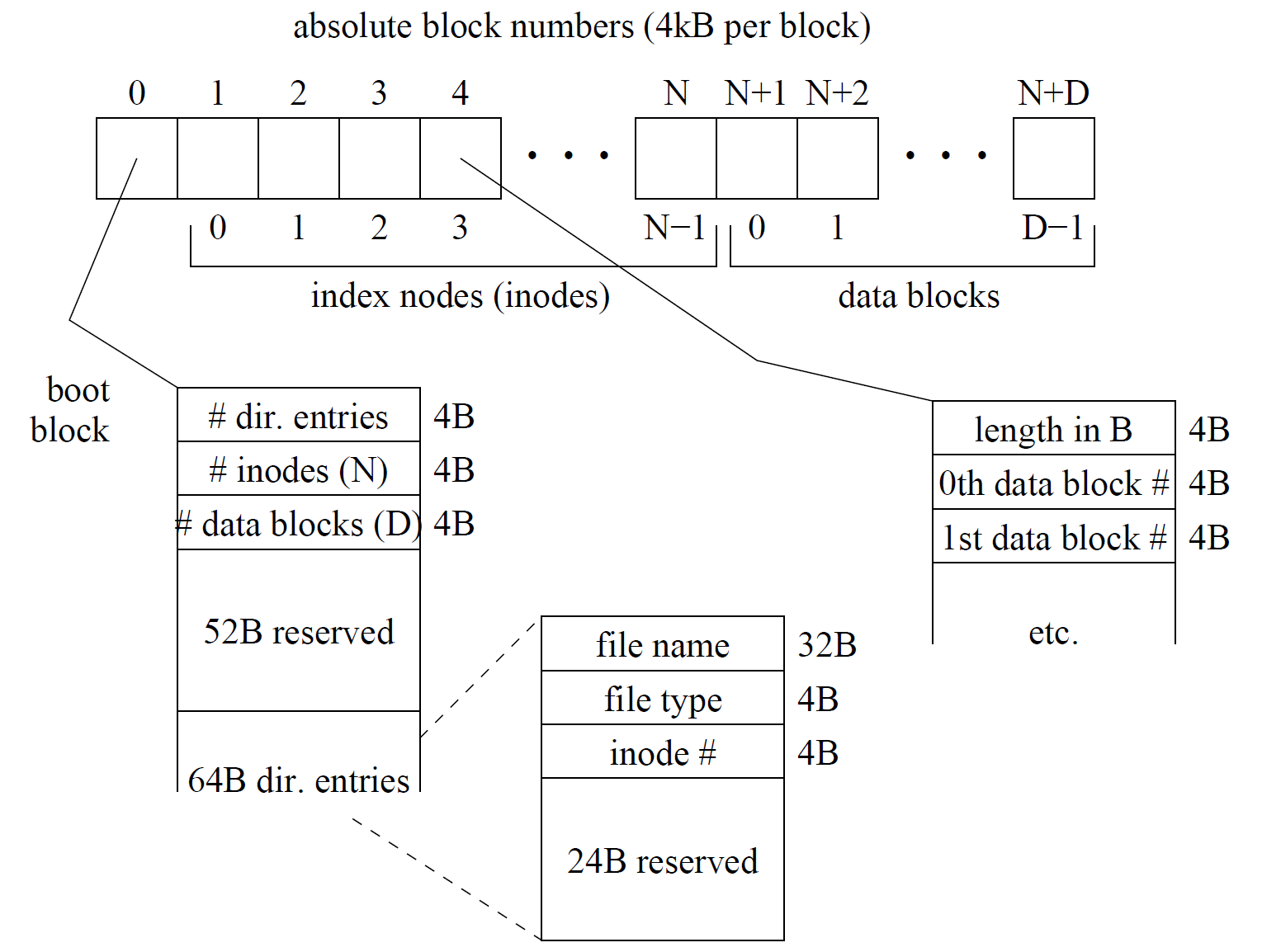
Each directory entry gives a name (up to 32 characters, zero-padded, but not necessarily including a terminal EOS or O-byte), a file type, and an index node number for the file. File types are 0 for a file giving user-level access to the real-time clock (RTC), 1 for the directory, and 2 for a regular file. The index node number is only meaningful for regular files and should be ignored for the RTC and directory types. Each regular file is described by an index node that specifies the file’s size in bytes and the data blocks that make up the file. Each block contains 4 kB; only those blocks necessary to contain the specified size need be valid, so be careful not to read and make use of block numbers that lie beyond those necessary to contain the file data.
int32_t read_dentry_by_name (const uint8_t* fname, dentry_t* dentry);
int32_t read_dentry_by_index (uint32_t index, dentry-t* dentry);
int32_t read_data (uint32_t inode, uint32_t offset, uint8_t* buf, uint32_t length);
The three routines provided by the file system module return -1 on failure, indicating a non-existent file or invalid
index in the case of the first two calls, or an invalid inode number in the case of the last routine. Note that the directory
entries are indexed starting with 0. Also note that the read_data call can only check that the given inode is within the
valid range. It does not check that the inode actually corresponds to a file (not all inodes are used). However, if a bad
data block number is found within the file bounds of the given inode, the function should also return -1.
When successful, the first two calls fill in the dentry_t block passed as their second argument with the file name, file
type, and inode number for the file, then return 0. The last routine works much like the read system call, reading up to
length bytes starting from position off set in the file with inode number inode and returning the number of bytes
read and placed in the buffer. A return value of 0 thus indicates that the end of the file has been reached.
File System Abstractions
Each task can have up to 8 open files. These open files are represented with a file array, stored in the process control block (PCB). The integer index into this array is called a file descriptor, and this integer is how user-level programs identify the open file.
This array should store a structure containing:
-
The file operations jump table associated with the correct file type. This jump table should contain entries for open, read, write, and close to perform type specific actions for each operation. open is used for performing type specific initialization. For example, if we just open’d the RTC, the jump table pointer in this structure should store the RTC’s file operations table.
-
The inode number for this file. This is only valid for data files, and should be 0 for directories and the RTC device file.
-
A “file position” member that keeps track of where the user is currently reading from in the file. Every read system call should update this member.
-
A “flags” member for, among other things, marking this file descriptor as “in-use.”
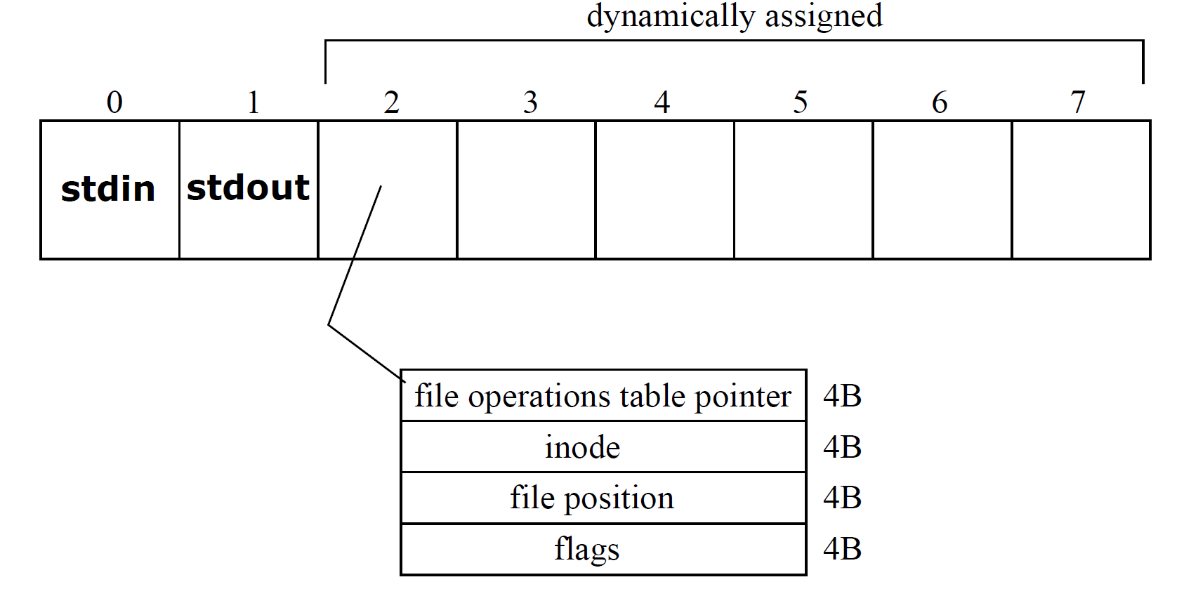
When a process is started, the kernel should automatically open stdin and stdout, which correspond to file descriptors O and 1, respectively. stdin is a read-only file which corresponds to keyboard input. stdout is a write-only
file corresponding to terminal output. “Opening” these files consists of storing appropriate jump tables in these two
locations in the file array, and marking the files as in-use. For the remaining six file descriptors available, an entry in
the file array is dynamically associated with the file being open‘d whenever the open system call is made (return -1 if
the array is full).
Appendix B: The System Calls #
You must support ten system calls, numbered 1 through 10. As with Linux, they are invoked using int 0x80, and
use a similar calling convention. In particular, the call number is placed in EAX, the first argument in EBX, then
ECX, and finally EDX. No call uses more than three arguments, although you should protect all of the registers from
modification by the system call to avoid leaking information to the user programs. The return value is placed in EAX
if the call returns (not all do); a value of -1 indicates an error, while others indicate some form of success.
Prototypes appear below. Unless otherwise specified, successful calls should return 0, and failed calls should return - 1.
int32_t halt (uint8_t status);int32_t execute (const uint8_t* command);int32_t read (int32_t fd, void* buf, int32_t nbytes);int32_t write (int32_t fd, const void* buf, int32_t nbytes);int32_t open (const uint8-t* filename);int32_t close (int32_t fd);int32_t getargs (uint8_t* buf, int32_t nbytes);int32_t vidmap (uint8_t** screen_start);int32_t set_handler (int32_t signum, void* handler_address);int32_t sigreturn (void);
The execute system call attempts to load and execute a new program, handing off the processor to the new program
until it terminates. The command is a space separated sequence of words. The first word is the file name of the
program to be executed, and the rest of the command stripped of leading spaces should be provided to the new
program on request via the getargs system call. The execute call returns -1 if the command cannot be executed,
for example, if the program does not exist or the filename specified is not an executable, 256 if the program dies by an
exception, or a value in the range 0 to 255 if the program executes a halt system call, in which case the value returned
is that given by the program’s call to halt.
The halt system call terminates a process, returning the specified value to its parent process. The system call handler
itself is responsible for expanding the 8-bit argument from BL into the 32-bit return value to the parent program’s
execute system call. Be careful not to return all 32 bits from EBX. This call should never return to the caller.
The read system call reads data from the keyboard, a file, device (RTC), or directory. This call returns the number
of bytes read. If the initial file position is at or beyond the end of file, 0 shall be returned (for normal files and the
directory). In the case of the keyboard, read should return data from one line that has been terminated by pressing
Enter, or as much as fits in the buffer from one such line. The line returned should include the line feed character.
In the case of a file, data should be read to the end of the file or the end of the buffer provided, whichever occurs
sooner. In the case of reads to the directory, only the filename should be provided (as much as fits, or all 32 bytes), and
subsequent reads should read from successive directory entries until the last is reached, at which point read should
repeatedly return 0. For the real time clock (RTC), this call should always return 0, but only after an interrupt has
occurred (set a flag and wait until the interrupt handler clears it, then return 0). You should use a jump table referenced
by the task’s file array to call from a generic handler for this call into a file type specific function. This jump table
should be inserted into the file array on the open system call (see below).
The write system call writes data to the terminal or to a device (RTC). In the case of the terminal, all data should
be displayed to the screen immediately. In the case of the RTC, the system call should always accept only a 4-byte
integer specifying the interrupt rate in Hz, and should set the rate of periodic interrupts accordingly. Writes to regular
files should always return -1 to indicate failure since the file system is read only. The call returns the number of bytes
written, or -1 on failure.
The RTC device itself can only generate interrupts at a rate that is a power of 2 (do a parameter check), and only
up to 8192 Hz. Your kernel should limit this further to 1024 Hz - an operating system shouldn’t allow userspace programs to generate more than 1024 interrupts per second by default. Look at drivers/char/rtc.c,
include/linux/mc146818rtc.h and possibly other associated header files for the macros and port numbers for
interfacing with the RTC device.
Note that you should be using the RTC’s Periodic Interrupt function to generate interrupts at a programmable rate. The
RTC interrupt rate should be set to a default value of 2 Hz (2 interrupts per second) when the RTC device is opened.
For simplicity, RTC interrupts should remain on at all times.
The open system call provides access to the file system. The call should find the directory entry corresponding to the
named file, allocate an unused file descriptor, and set up any data necessary to handle the given type of file (directory,
RT C device, or regular file). If the named file does not exist or no descriptors are free, the call returns -1.
The close system call closes the specified file descriptor and makes it available for return from later calls to open.
You should not allow the user to close the default descriptors (O for input and l for output). Trying to close an invalid
descriptor should result in a return value of -l; successful closes should return 0.
The getargs call reads the program’s command line arguments into a user-level buffer. Obviously, these arguments
must be stored as part of the task data when a new program is loaded. Here they are merely copied into user space.
If the arguments and a terminal NULL (O-byte) do not fit in the buffer, simply return -1. The shell does not request
arguments, but you should probably still initialize the shell task’s argument data to the empty string.
The vidmap call maps the text-mode video memory into user space at a preset virtual address. Although the address
returned is always the same (see the memory map section later in this handout), it should be written into the memory
location provided by the caller (which must be checked for validity). If the location is invalid, the call should return -1.
To avoid adding kernel side exception handling for this sort of check, you can simply check whether the address falls
within the address range covered by the single userlevel page. Note that the video memory will require you to add
another page mapping for the program, in this case a 4 kB page. It is not ok to simply change the permissions of the
video page located < 4MB and pass that address.
The set_handler and sigreturn calls are related to signal handling and are discussed in the section Signals below.
Even if your operating system does not support signals, you must support these system calls; in such a case, however,
you may immediately return failure from these calls.
Note that some system calls need to synchronize with interrupt handlers. For example, the read system call made on
the RTC device should wait until the next RTC interrupt has occurred before it returns. Use simple volatile flag variables to do this synchronization (e.g., something like int rtc_interrupt_occurred;) when possible (try some
thing more complicated only after everything works!), and small critical sections with cli/sti. For example, writing
to the RT C should block interrupts to interact with the device. Writing to the terminal also probably needs to block
interrupts, if only briefly, to update screen data when printing (keyboard input is also printed to the screen from the
interrupt handler).
Appendix C: Memory Map and Task Specification #
When processing the execute system call, your kernel must create a virtual address space for the new process. This will involve setting up a new Page Directory with entries corresponding to the figure shown on the right. The virtual memory map for each task is show in the figure. The kernel is loaded at physical address 0x400000 (4 MB), 128MB and also mapped at virtual address 4 MB. A global page directory entry with its Supervisor bit set should be set up to map the kernel to virtual address ox400000 (4 MB). This ensures that the kernel, which is linked to run with its starting address at 4 MB, will continue to work even after paging is turned on.
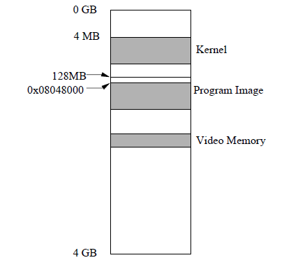
To make physical memory management easy, you may assume there is at least 16 MB of physical memory on the system. Then, use the following (static) strategy: the first user-level program (the shell) should be loaded at physical 8 MB, and the second user-level program, when it is executed by the shell, should be loaded at physical 12 MB. The program image itself is linked to execute at virtual address 0x08048000. The way to get this working is to set up a single 4 MB page directory entry that maps virtual address 0x08000000 (128 MB) to the right physical memory address (either 8 MB or 12 MB). Then, the program image must be copied to the correct offset (0x00048000) within that page.
Both the kernel mapping and the user-level program mapping are critical; memory references in neither the kernel nor the program will not work correctly unless they are mapped at these exact addresses.
The layout of executable files in the file system is simple: the entire file stored in the file system is the image of the program to be executed. In this file, a header that occupies the first 40 bytes gives information for loading and starting the program. The first 4 bytes of the file represent a “magic number” that identifies the file as an executable. These bytes are, respectively, 0: 0x7f; 1: 0x45; 2: 0x4c; 3: 0x46. If the magic number is not present, the execute system call should fail. The other important bit of information that you need to execute programs is the entry point into the program, i.e., the virtual address of the first instruction that should be executed. This information is stored as a 4-byte unsigned integer in bytes 24-27 of the executable, and the value of it falls somewhere near 0x08048000 for all programs we have provided to you. When processing the execute system call, your code should make a note of the entry point, and then copy the entire file to memory starting at virtual address 0x08048000. It then must jump to the entry point of the program to begin execution. The details of how to jump to this entry point are explained in the next section.
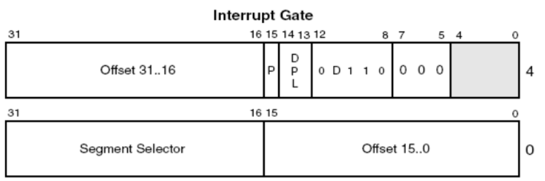
Appendix D: System Calls, Exceptions, and Interrupts #
Recall that when a hardware interrupt is asserted or a hardware exception is detected, a specific number is associated with the exception or interrupt to differentiate between different types of exceptions, or different hardware devices (for example, differentiating between the keyboard interrupt, the network card interrupt, and a divide-by-zero exception). This number is used to index a table, called the Interrupt Descriptor Table, or IDT. The format of an IDT entry is shown in the figure below, and the details of it are found in the Intel architecture manuals (see the “Getting Started” section for more info on references). Each IDT entry contains, among other things, a pointer to the corresponding interrupt handler function to be run when that interrupt is received. When an exception or hardware interrupt is detected, the processor switches into privilege level 0 (kernel mode), saves some, but not all of the processor registers on the kernel stack (see Appendix E for more details), and jumps to the function address specified in the entry. Now, kernel code, specifically the interrupt handler for the correct interrupt number, is now executing.
For system calls, you will use a similar mechanism. A user-level program will execute a int $0x80 instruction. The
int instruction functions similar to an exception. It specifies that the processor should use entry 0x80 in the IDT
as the handler when this instruction is executed. The same privilege-level switching, stack switching, etc, are all
performed, so after this instruction is run, kernel code will be executing. You must set up a “system call handler” IDT
entry at index ox80, as well as a function that will be run for all system calls. This function can then differentiate
different system calls based on the parameter passed in EAX.
For this to work properly, you must pay attention to a few details of the x86 architecture and protection scheme when setting up the IDT. The IDT will contain entries for exception handlers, hardware interrupt handlers, and the system call handler. Each entry in the IDT has a Descriptor Privilege Level (DPL) that specifies the privilege level needed to use that descriptor. Hardware interrupt handlers and exception handlers should have their DPL set to 0 to prevent user-level applications from calling into these routines with the int instruction. The system call handler should have its DPL set to 3 so that it is accessible from user space via the int instruction. Finally, each IDT entry also contains a segment selector field that specifies a code segment in the GDT, and you should set this field to be the kernel’s code segment descriptor. When the x86 sees that a new CS is specified, it will perform a privilege switch, and the handler for the IDT entry will run in the new privilege level. This way, the system call interface is accessible to user space but the code executes in the kernel.
Appendix E: Stack Switching and the TSS #
The last detail of user space to kernel transitions on system calls, interrupts, or exceptions is stack switching. The stack switch is taken care of by the x86 hardware. The x86 processor supports the notion of a task; this hardware support is encapsulated in a Task State Segment, or TSS. You will not use the full x86 hardware support for tasks in this project, but the x86 requires that you set up one TSS for, among other things, privilege level stack switching. The TSS in the given code is a placeholder. Read the Intel manuals for details on the fields in it; the important fields are 880 and ESPO. These fields contain the stack segment and stack pointer that the x86 will put into SS and ESP when performing a privilege switch from privilege level 3 to privilege level 0 (for example, when a user-level program makes a system call, or when a hardware interrupt occurs while a user-level program is executing). These fields must be set to point to the kernel’s stack segment and the process’s kernel-mode stack, respectively. Note that when you start a new process, just before you switch to that process and start executing its user-level code, you must alter the TSS entry to contain its new kernel-mode stack pointer. This way, when a privilege switch is needed, the correct stack will be set up by the x86 processor.
Appendix F: Signals #
For extra credit, your OS can provide an infrastructure for user-level signals, similar to Linux. The table details the signals that will be supported.
| Signal Name | Signal Number | Default Action |
|---|---|---|
| DIV_ZERO | 0 | Kill The Task |
| SEGFAULT | 1 | Kill The Task |
| INTERRUPT | 2 | Kill The Task |
| ALARM | 3 | Ignore |
| USER1 | 4 | Ignore |
The set_handler system call changes the default action taken when a signal is received: the signum parameter
specifies which signal’s handler to change, and the handler-address points to a user-level function to be run when
that signal is received. It returns 0 if the handler was successful set, and -1 on failure. If handler-address is NULL
(zero), the kernel should reset the action taken to be the default action.
DIV_ZERO should be sent to a task when the x86 processor generates a divide-by-zero exception while executing user-level code. SEGFAULT should be sent when any other exception occurs, including any illegal instructions, illegal memory references, page faults, general protection faults, illegal opcodes, etc. The INTERRUPT signal should be sent when a CT RL+C is pressed on the keyboard. The ALARM signal should be sent to the currently-executing task (there is only one currently-executing task in this OS) every 10 seconds. This should be implemented by knowing at what rate the RTC’s Periodic Interrupts occur, counting how many Periodic Interrupts have occurred, and sending an ALARM signal after 10 seconds have elapsed. Finally, USER1 is user-defined and can be used to implement any other signal of your choosing.
Signals should only be delivered to a task when returning to user space from the kernel, so you’ll want to add some code in your return-to-user space linkage to check for pending signals. To support signal delivery, you should use a mechanism similar to what Linux uses:
-
Mask all other signals.
-
Set up the signal handler’s stack frame. You’ll need the current value of the user-level ESP register to find the user’s current stack location. The signal handler stack frame goes directly above this on the stack. The signal handler stack frame is shown in Figure 1. Setting up the signal handler stack frame involves: copying a return address and a signal number parameter to the user-level stack, copying the process’s hardware context (see Figure 2) from the point when the program was interrupted for the signal, and copying a small amount of assembly linkage to the user-level stack that calls
sigreturnwhen the signal handler is finished. -
Finally, execute (in user space) the handler specified in the signal descriptor. No other information needs to be passed to the signal handler (no
siginfo_tstructure like the modern Linux signals).
When the user-level signal handler returns, it will use the return address you have copied on its stack, which will jump
to the assembly linkage (also on the stack). This assembly linkage should make the sigreturn system call (using the
standard int $0x80 user-level system call calling convention).
The sigreturn system call should copy the hardware context that was on the user-level stack back onto the processor.
To find the hardware context, you will need to know the user-level value of ESP (will be saved by your system call
handler) as well as the exact setup of the user-level stack frame. To copy the hardware context back onto the processor,
you will actually overwrite the kernel’s copy of the process’s hardware context that was saved on the kernel stack when
it handled the sigreturn system call. In this way, when the sigreturn system call handler returns to user space,
the hardware context will automatically be copied back onto the processor by your return-from-kernel code that you
have already written. One thing to be careful of: you’ll probably have system calls set up to return a value (in EAX)
to user space. Be sure you don’t clobber the user’s EAX value from its hardware context with a bogus “return value”
From sigreturn - have sigreturn return the hardware context’s EAX value so that you won’t have to special-case
the return from sigreturn.
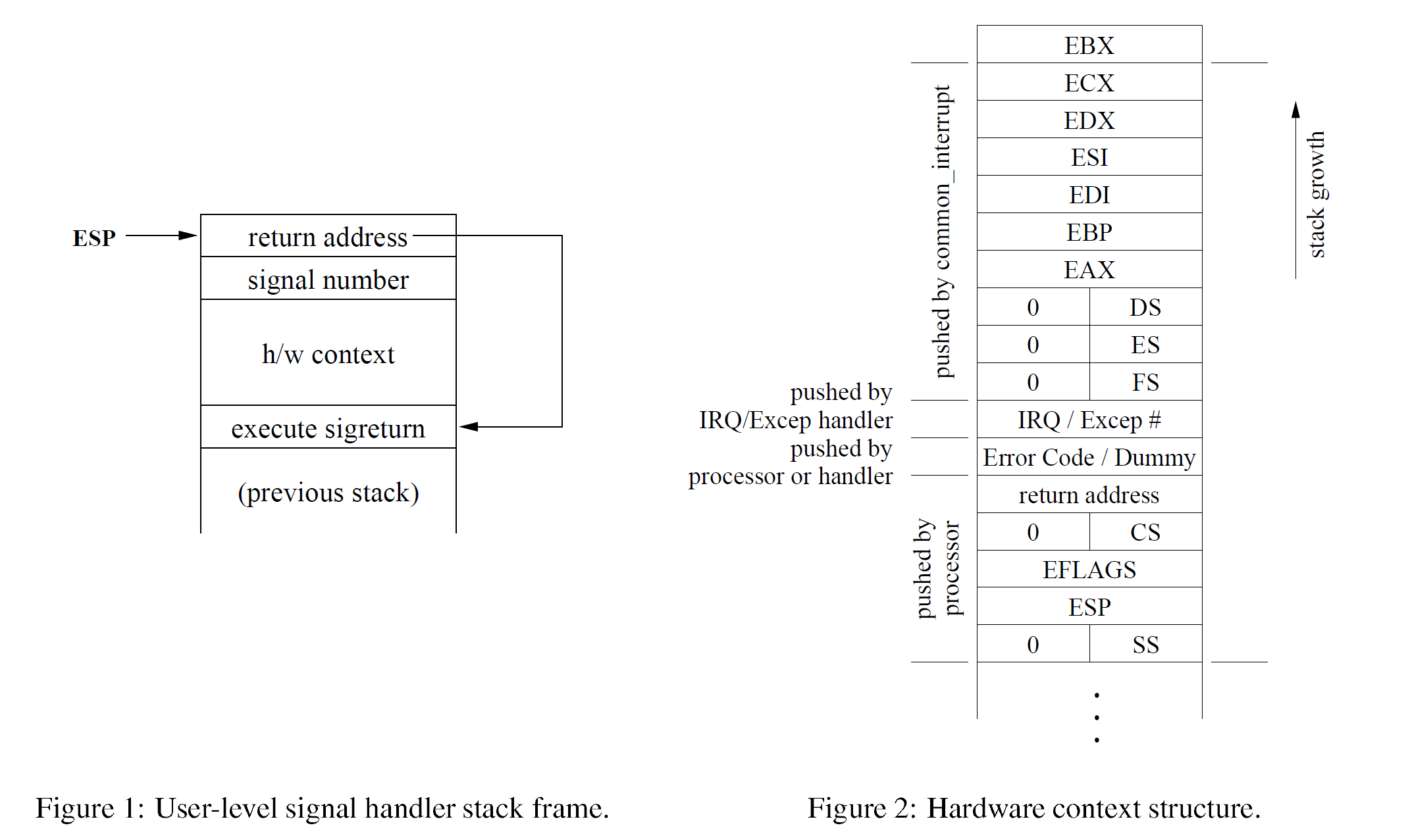
Shown in Figure 2 is a slightly-modified version of the struct pt_regs structure that Linux uses for its hardware context; this modified structure is what you should use in this MP. The “Error Code / Dummy” field has been added to the hardware context to simplify exception handling. For some exceptions, the processor pushes an error code onto the stack after XCS (for example, page faults do) whereas other exceptions do not (divide-by-zeros do not). For exceptions that do not push this error code, your exception handler should push a dummy value to take up the error code slot3. x86 interrupts never push the error code, so you must also push a dummy value in all of your interrupt handlers and the system call handler. You can find documentation about which exceptions push error codes (and much more about exceptions) in Volume 11: System Programming of the Intel ISA manual on the Tools, References, and Links section of the website.
Finally, signal handling information should go in the process control block (PCB). You will need to keep track of pending signals, masked signals, and handler actions / addresses for each signal. Much information on Linux’s implementation of signals (which your implementation will closely match) can be found in Understanding the Linux Kernel chapter 10.
Alternative (with video) #
Please watch this introductory video to linux kernels before you begin.
There is no lab assignment, just do the review. It will not be graded.